
Everything is now installed, go ahead and power your printer back on.
The Broadcast Board comes preloaded with WLED, an open-source LED controller firmware. As soon as the board receives power, it will boot into AP mode (Access Point mode), which creates a temporary Wi-Fi network that you’ll see on your phone or laptop.
There are two easy ways to connect:
WLED-native App (iOS or Android) - recommended for easiest setup
Web Browser - go directly to the WLED interface
Initial Setup
On your phone or laptop, open Wi-Fi settings and connect to the WLED-AP network. Default password: wled1234
Once connected, open the WLED app or type http://4.3.2.1/ in your browser’s address bar.
You should now see the WLED interface!
If WLED-AP does not show up as an available wifi network, click the reset button and/or pull the AMS cable to power cycle the board
From here, you can either:
Keep the board in AP mode and use it locally, or
Connect it to your home Wi-Fi by going to Config > WiFi Settings, entering your network name and password, and hitting save.
The board will reboot after connecting.
In the browser, you’ll need to check your router to find the new IP address.
In the app, refresh the device list - you should see the board appear with its new IP.
Once connected, you’re ready to explore all of WLED’s features. By default there is a preloaded preset called "Bright White" which will apply after reboot
The following LED settings are set before shipment. But if you experience any problems with the LEDs not turning on or off, check these settings and check out the WLED documentation.
WLED Config ⚙️ > LED Preferences
LED type & length: WS2805 RGBCW (for kit LEDs)
Length: 22
Data GPIO: 10
Button 0 GPIO: 3 (Switch)
Relay GPIO: 5
And that’s it, your new lighting system is up and running! Any questions please email at skylakelabs1@gmail.com
WLED firmware v0.15.0 - Link to GitHub
© 2016-present Christian Schwinne and contributors
Licensed under the European Union Public Licence (EUPL) v 1.2 or later.
Skylake Lighting System
WLED Setup
Lighting System Assembly
To assemble the lighting system, start by printing the Skylake LED riser from MakerWorld or Thangs. Remove all supports and snap the four pieces together. Slide the sense cable into its built-in channel, leaving 3–4 inches exposed to reach the stock LED header. TIP - use a piece of filament to help push the cable through the channel. (Diagrams at the bottom of this page)
Important: Do not peel the adhesive backing on the LED strip. Instead, slide the LED strip into the designated slots in the riser, making sure the arrows on the strip match the orientation shown in the diagram below.
If you’re using the Solder-Free Kit, simply plug in all three connectors and snap them into the corner holders.
If you’re using the DIY Kit:
Place the wires in the corners and mark where each should be cut.
Use the dashed wire for 12 V.
Strip and tin both ends of each wire, as well as the LED strip pads.
Solder the wires to the strip:
Dashed wire → 12V
Do → Din
Bo → Din
GND → GND
The long 3-conductor wire runs back to the Broadcast Board. I also recommend stripping and tinning those ends before plugging them into the board for a cleaner, more secure connection.
Solder the long wire to the first LED strip:
Dashed wire → 12V
Middle wire → Din and Bin (yes bridge both pads with the same wire)
Third wire → GND
Printer Installation
Before you begin: Make sure the printer is unplugged.
Once the lighting system is assembled, feed the wires through the pass-through slot at the back of the riser. Flip the riser over and place it on top of the printer.
Locate the stock LED header, unplug the existing cable, and gently tuck it away. Plug the sense cable into the stock LED header, route the cable neatly into the corner channel, and pull back any slack toward the back of the printer. For help locating the stock LED header, refer to the Bambu Lab Wiki for your specific model (P1S or X1C).
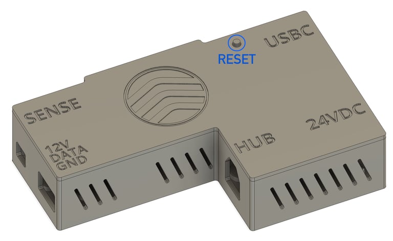
Carefully remove the cover from the Broadcast Board enclosure, and take note of the small reset button shaft - set it aside for now.
Peel the adhesive backing from the enclosure and mount it just above the AMS hub/buffer.
Take the long 3-wire cable from the LED strip and connect it to the terminal block on the Broadcast Board. Use the labels on the enclosure lid to guide you:
Top terminal: Dashed wire → 12V
Middle terminal: Middle wire → Data
Bottom terminal: Third wire → GND
Tighten the screws on the terminal block just enough to hold the wires securely - do not overtighten.
Next, plug in the sense cable and both AMS cables (Diagram below):
Right side: Connect the AMS cable from the printer
Left side: Connect the AMS cable going to the AMS hub/buffer
Finally, ensure the reset button shaft is aligned and seated properly, then replace the cover on the enclosure.
FAQ
What if I don't see the WLED-AP wifi network when I power on the board?
If booting for the first time.
Press the reset button located on the top of the enclosure
If you still don't see it, unplug and re plug the AMS cable
If WIFI credentials have already been entered.
You will no longer see the WLED-AP if it has connected to your network.
Easy Method: Download the WLED mobile app, connect your device to the same WIFI network, and scan.
Advanced Method: Log onto your home WIFI router to find the device's IP address. Go type the IP into your web browser to take control of the device.
If the app is giving you trouble, kill the app, turn on and off WIFI on device and re launch the app (sometimes it needs a little help)
The board is not behaving as expected?
Press the reset button for 0.5s and allow a few seconds to reboot
Test the basic board functionality. By default the board is programmed to toggle on and off the LEDs whether or not its connected to WIFI. Toggle on and off the LEDs with the printer controls to see if it behaves correctly.
Take a look at the PCB, is there a green light?
Yes - The board is powered correctly
No - The board is not getting correct power, check the connection to the AMS port on the printer.
The LEDs are not behaving as expected?
Press the reset button for 0.5s and allow a few seconds to reboot
Toggle on and off the LEDs with the printer controls to see if it behaves correctly.
Take a look at the wires from LED strip 1 to the board.
The wire with the dashes should be connected to the 12V terminal (look at the text on the lid).
The middle wire should be connected to the middle terminal labeled DATA
The third wire on the end with no dashes should be connected to GND
Still having trouble?
Please don't hesitate to reach out to me directly at
skylakelabs1@gmail.com
You will hear back from me, not an automated message or AI bot.
We will troubleshoot together and get your system up and running. We will do some basic checks and if we determine any part of the system is faultly, we will get more parts sent your way!
What is the USBC port for?
This is used for programming the device, it will not power on the LEDS.
It will still power the MCU and you should be able to interact with the WLED controls, this can be used to troubleshoot the system if needed.
Diagrams

